The first five posts of these series were largely conceptual discussions that sprinkled in some SQL and data models here and there where helpful. This final post will serve as a summary of those posts, but it will also specifically include SQL queries, data models and transformation logic related to the overall discussion that should hopefully help you in your data engineering and analytics journey.
(Some of the content below has already been shared as-is, other content below iterates on what’s already been reviewed, and some is net new.)
And while this series of posts is specifically about hierarchies, I’m going to include SQL code for modeling graphs and DAGs as well just to help further cement the graph theory concepts undergirding hierarchies. As you’ll see, I’m going to evolve the SQL data model from one step to the next, so you can more easily see how a graph is instantiated as a DAG and then as a hierarchy.
I’m also going to use fairly generic SQL including with less commonly found features such as UNIQUE constraints. I’m certainly in the minority camp of Data Engineers that embrace the value offered by such traditional capabilities (which aren’t even supported in modern features such as Snowflake hybrid tables), and so while you’re unlikely to be able to implement some of the code directly as-is in a modern cloud data warehouse, they succinctly/clearly explain how the data model should function (and more practically indicate where you’ll need to keep data quality checks in mind in the context of your data pipelines, i.e. to basically check for what such constraints should be otherwise enforced).
And lastly, as alluded to in my last post, I’m not going to over-complicate the model. There are real-world situations that require modeling hierarchies either in a versioned approach or as slowly-changing dimensions, but to manage scope/complexity, and to encourage you to coordinate and learn from your resident Data Architect (specifically regarding the exact requirements of your use case), I’ll hold off on providing specific SQL models for such particularly complex cases. (If you’re a Data Architect reading this article, with such a use case on your hands, and you could use further assistance, you’re more than welcome to get in touch!)
Graphs
Hierarchies are a subset of graphs, so it’s helpful to again summarize what graphs are, and discuss how they can be modeled in a relational database.
A graph is essentially a data structure that captures a collection of things and their relationships to one another.
- A graph is also often referred to as a network.
- A “thing” is represented by a node in a graph, which is sometimes called a vertex in formal graph theory (and generally corresponds with an entity [i.e. a table] in relational databases, but can also correspond with an attribute [i.e. a column] of an entity).
- The relationship between two nodes is referred to as an edge, and two such nodes can have any number of edges.
- A node, quite obviously (as an entity) can have any number of attributes associated with it (including numerical attributes used in sophisticated graph algorithms [such as “biases” found in the graph structures of neural networks]).
- Oftentimes an edge is directed in a particular way (i.e. one of the nodes of the edge takes some kind of precedence over the other, such as in a geospatial sense, chronological sense, or some other logical sense).
- Edges often map to entities as well, and thus can have their own attributes. (Since LLMs are so popular these days, it’s perhaps worth pointing out how “weights” in neural networks are examples of numerical attributes associated with edges in a (very large) graph]).
Following is a basic data model representing how to store graph data in a relational database.
(It’s suggested you copy this code into your favorite text editor as .sql file for better formatting / syntax highlighting).
Modeling Graphs
Here is a basic data model for generic graphs. It consists of two tables:
- one for edges
- another for nodes (via a generic ENTITY table)
(It’s certainly possibly you’d also have a header GRAPH table that, at a minimum, would have a text description of what each graph represents. The GRAPH_ID below represents a foreign key to such a table. It’s not included here simply due to the fact that this model will evolve to support hierarchies which I usually denormalize such header description information directly on to.)
/*ENTITY_ID_NAME, -- Name of your natural key.
Graph nodes represent real world entities/dimensions.
This is just a placeholder table for such entities, i.e.
your real-world GRAPH_EDGE table would likely reference your master data/dimension
tables directly.
*/
CREATE TABLE NODE_ENTITY
(
ID INT, -- Technical primary key.
ENTITY_ID_VALUE, -- Value of your natural key.
ENTITY_ATTRIBUTES VARIANT, -- Placeholder for all relevant attributes
PRIMARY KEY (ID),
UNIQUE(ENTITY_NAME, ENTITY_ID)
);/*
Graph edges with any relevant attributes.
Unique constraint included for data quality.
- Multiple edges are supported in graphs
- But something should distinguish one such edge from another.
Technical primary key for simpler joins / foreign keys elsewhere.
*/
CREATE TABLE GRAPH_EDGE
(
ID INT, -- Technical primary key (generated, i.e. by a SEQUENCE)
GRAPH_ID INT, -- Identifier for which graph this edge belongs to
NODE_ID_1 INT NOT NULL,
NODE_ID_2 INT NOT NULL,
DIRECTION TEXT, -- Optional. Valid values: FROM/TO.
EDGE_ID INT NOT NULL, -- Unique identifier for each edge
EDGE_ATTRIBUTES VARIANT, -- Placeholder for all relevant attributes
-- constraints,
PRIMARY KEY (ID),
UNIQUE (GRAPH_ID, EDGE_ID, NODE_1, NODE_2)
FOREIGN KEY (NODE_ID_1) REFERENCES NODE_ENTITY (ID),
FOREIGN KEY (NODE_ID_2) REFERENCES NODE_ENTITY (ID),
CHECK (DIRECTION IN ('FROM', 'TO'))
);
DAGs
A directed acyclic graph, or DAG, represents a subset of graphs for which:
- Each edge is directed
- A given node cannot reach itself (i.e. traversing its edges in their respective directions will never return to node from which such a traversal started).
As such, a relational model should probably introduce three changes to accommodate the definition of a DAG:
- To simplify the model (and remove a potential data quality risk), it probably makes sense to remove the DIRECTION column and rename the node ID columns to NODE_FROM_ID and NODE_TO_ID (thereby capturing the edge direction through metadata, i.e. column names).
- The relational model doesn’t have a native way to constrain cycles, so a data quality check would need to be introduced to check for such circumstances.
- Technically, a DAG can have multiple edges between the same two nodes. Practically, this is rare, and thus more indicative of a data quality problem – so we’ll assume it’s reasonable to go ahead and remove that possibility from the model via a unique constraint (although you should confirm this decision in real life if you need to model DAGs.)
-- Renamed from GRAPH_EDGE
CREATE TABLE DAG_EDGE
(
    ID INT,
    DAG_ID,                    -- Renamed from GRAPH_ID
    NODE_FROM_ID INT NOT NULL, -- Renamed from NODE_1
    NODE_TO_ID INT NOT NULL,   -- Renamed from NODE_2
    EDGE_ATTRIBUTES VARIANT,
    PRIMARY KEY (ID),
    UNIQUE (GRAPH_ID, NODE_1, NODE_2)
);
Hierarchies (Parent/Child)
A hierarchy is a DAG for which a given (child) node only has a single parent node (except for the root node, which obviously has no parent node).
The concept of a hierarchy introduces a few particularly meaningful attributes (which have much less relevance to graphs/DAGs) that should be included in our model:
- LEVEL: How many edges there are between a given node and its corresponding root node, i.e. the “natural” level of this node.
- This value can be derived recursively, so it need not strictly be persisted — but it can drastically simplify queries, data quality checks, etc.
- NODE_TYPE: Whether a given node is a root, inner or leaf node.
- Again, this can be derived, but its direct inclusion can be incredibly helpful.
- SEQNR: The sort order of a set of “sibling” nodes at a given level of the hierarchy.
It’s also worth introducing a HIERARCHY_TYPE field to help disambiguate the different kind of hierarchies you might want to store (i.e. Profit Center, Cost Center, WBS, Org Chart, etc.). This isn’t strictly necessary if your HIERARCHY_ID values are globally unique, but practically speaking it lends a lot of functional value for modeling and end user consumption.
And lastly, we should rename a few fields to better reflect the semantic meaning of a hierarchy that distinguishes it from a DAG.
Note: the following model closely resembles the actual model I’ve successfully used in production at a large media & entertainment company for a BI use cases leveraging a variant of MDX.
-- Renamed from DAG_EDGE
CREATE TABLE HIERARCHY
(
ID INT,-- Technical primary key (generated, i.e. by a SEQUENCE)
HIERARCHY_TYPE TEXT, -- I.e. PROFIT_CENTER, COST_CENTER, etc.
HIERARCHY_ID INT, -- Renamed from DAG_ID
PARENT_NODE_ID INT, -- Renamed from NODE_FROM_ID
CHILD_NODE_ID INT, -- Renamed from NODE_TO_ID
NODE_TYPE TEXT, -- ROOT, INNER or LEAF
LEVEL INT, -- How many edges from root node to this node
SEQNR INT, -- Ordering of this node compared to its siblings
PRIMARY KEY (ID),
UNIQUE (HIERARCHY_TYPE, HIERARCHY_ID, CHILD_NODE_ID)
);
Now, it’s worth being a bit pedantic here just to clarify a few modeling decisions.
First of all, this table is a bit denormalized. In terms of its granularity, it denormalizes hierarchy nodes, with hierarchy instances, with hierarchy types. Thus, this table could be normalized out into at least 3 such tables. In practice, the juice just isn’t worth the squeeze for a whole variety of reasons (performance among them).
Also, to avoid confusion for end users, the traditional naming convention for relational tables (i.e. including the [singular] for what a given record represents) is foregone in favor of simply calling it just HIERARCHY. (Not only does this better map to user expectations, especially with a denormalized model, but also corresponds with the reality that we’re capturing a set of records that have a recursive relationship to one another, which in sum represent the structure of a hierarchy as a whole, and not just the individual edges.)
Hierarchies (Level)
The parent/child model for hierarchies can be directly consumed by MDX, but given the prevalence of SQL as the query language of choice for “modern” BI tools and cloud data warehouses, it’s important to understand how to “flatten” a parent/child hierarchy, i.e. transform it into a level hierarchy.
Such a level hierarchy has a dedicated column for each level (as well as identifying fields for the hierarchy type and ID, and also a dedicated LEAF_NODE column for joining to fact tables). The LEVEL attribute is represented in the metadata, i.e. the names of the columns themselves, and its important to also flatten the SEQNR column (and typically TEXT description columns as well).
(Remember that this model only reflects hierarchies for which fact table foreign keys always join to the leaf nodes of a given hierarchy. Fact table foreign keys that can join to inner nodes of a hierarchy are out of scope for this discussion.)
CREATE TABLE LEVEL_HIERARCHY
(
    ID INT,
    HIERARCHY_TYPE TEXT,
    HIERARCHY_ID INT,    -- Renamed from DAG_ID. Often equivalent to ROOT_NODE_ID.
    HIERARCHY_TEXT TEXT, -- Often equivalent to ROOT_NODE_TEXT.
    ROOT_NODE_ID INT,    -- Level 0, but can be considered LEVEL 1.
    ROOT_NODE_TEXT TEXT,
    LEVEL_1_NODE_ID INT,
    LEVEL_1_NODE_TEXT TEXT,
    LEVEL_1_SEQNR TEXT,
    LEVEL_2_NODE_ID INT,
    LEVEL_2_NODE_TEXT TEXT,
    LEVEL_2_SEQNR TEXT,
    ...
    LEVEL_N_NODE_ID INT,
    LEVEL_N_NODE_TEXT TEXT,
    LEVEL_N_SEQNR TEXT,
    LEAF_NODE_ID           -- Joins to fact table on leaf node
    PRIMARY KEY (ID),
    UNIQUE (HIERARCHY_TYPE, HIERARCHY_ID, LEAF_NODE_ID)
);
Remember that level hierarchies come with the inherent challenge that they require a hard-coded structure (in terms of how many levels they represent) whereas a parent/child structure does not. As such, a Data Modeler/Architect has to make a decision about how to accommodate such data.
- If some hierarchies are expected to rarely change, then a strict level hierarchy with the exact number of levels might be appropriate.
- If other hierarchies change frequently (such as product hierarchies in certain retail spaces), then it makes sense to add additional levels to accommodate a certain amount of flexibility, and to then treat the empty values either as a ragged or unbalanced (see following sections below).
- Again, recall that some level of flexibility can be introduced by leveraging views in your consumption layer. One example of benefits of this approach is to project only those level columns applicable to a particular hierarchy / hierarchy instance, while the underlying table might persist many more to accommodate many different hierarchies.
Now, how does one go about flattening a parent/child hierarchy into a level hierarchy? There are different ways to do so, but here is one such way.
- Use recursive logic to “flatten” all of the nodes along a given path into a JSON object.
- Use hard-coded logic to parse out the nodes of each path at different levels into different columns.
Here is sample logic, for a single hierarchy, that you can execute directly in Snowflake as is.
(Given the unavoidable complexity of this flattening logic, I wanted to provide this code as is that readers can run directly without any real life data, so that they can immediately see the results of this logic in action.)
To extend this query to accommodate the models above, make sure you add joins HIERARCHY_ID and HIERARCHY_TYPE.
CREATE OR REPLACE VIEW V_FLATTEN_HIER AS
WITH
    _cte_PARENT_CHILD_HIER AS
    (
        SELECT NULL AS PARENT_NODE_ID, 'A' AS CHILD_NODE_ID, 0 AS SEQNR UNION ALL
        SELECT 'A' AS PARENT_NODE_ID, 'B' AS CHILD_NODE_ID, 1 AS SEQNR UNION ALL
        SELECT 'A' AS PARENT_NODE_ID, 'C' AS CHILD_NODE_ID, 2 AS SEQNR UNION ALL
        SELECT 'B' AS PARENT_NODE_ID, 'E' AS CHILD_NODE_ID, 1 AS SEQNR UNION ALL
        SELECT 'B' AS PARENT_NODE_ID, 'D' AS CHILD_NODE_ID, 2 AS SEQNR UNION ALL
        SELECT 'C' AS PARENT_NODE_ID, 'F' AS CHILD_NODE_ID, 1 AS SEQNR UNION ALL
        SELECT 'F' AS PARENT_NODE_ID, 'G' AS CHILD_NODE_ID, 1 AS SEQNR
    )
    /*
        Here is the core recursive logic for traversing a parent-child hierarchy
        and flattening it into an array of JSON objects, which can then be further
        flattened out into a strict level hierarchy.
    */
    ,_cte_FLATTEN_HIER_INTO_OBJECT AS
    (
        -- Anchor query, starting at root nodes
        SELECT
            PARENT_NODE_ID,
            CHILD_NODE_ID,
            SEQNR,
            -- Collect all of the ancestors of a given node in an array
            ARRAY_CONSTRUCT
            (
                /*
                    Pack together path of a given node to the root node (as an array of nodes)
                    along with its related attributes, i.e. SEQNR, as a JSON object (element in the array)
                */
                OBJECT_CONSTRUCT
                (
                    'NODE', CHILD_NODE_ID,
                    'SEQNR', SEQNR
                )
            ) AS NODE_LEVELS
        FROM
            _cte_PARENT_CHILD_HIER
        WHERE
            PARENT_NODE_ID IS NULL -- Root nodes defined as nodes with NULL parent

        UNION ALL

        -- Recursive part: continue down to next level of a given node
        SELECT
            VH.PARENT_NODE_ID,
            VH.CHILD_NODE_ID,
            CP.SEQNR,
            ARRAY_APPEND
            (
                CP.NODE_LEVELS,
                OBJECT_CONSTRUCT
                (
                    'NODE', VH.CHILD_NODE_ID,
                    'SEQNR', VH.SEQNR
                )
            ) AS NODE_LEVELS
        FROM
            _cte_PARENT_CHILD_HIER VH
        JOIN
            _cte_FLATTEN_HIER_INTO_OBJECT CP
        ON
            VH.PARENT_NODE_ID = CP.CHILD_NODE_ID -- This is how we recursively traverse from one parent to its children
    )
    SELECT
        NODE_LEVELS
    FROM
        _cte_FLATTEN_HIER_INTO_OBJECT
    /*
        For most standard data models, fact table foreign keys for hierarchies only
        correspond with leaf nodes. Hence filter down to leaf nodes, i.e. those nodes
        that themselves are not parents of any other nodes.
    */
    WHERE
        NOT CHILD_NODE_ID IN (SELECT DISTINCT PARENT_NODE_ID FROM _cte_FLATTEN_HIER_INTO_OBJECT);

SELECT * FROM V_FLATTEN_HIER;
And then, to fully flatten out the JSON data into its respective columns:
WITH CTE_LEVEL_HIER AS
(
    /*
        Parse each value, from each JSON key, from each array element,
        in order to flatten out the nodes and their sequence numbers.
    */
    SELECT
        CAST(NODE_LEVELS[0].NODE AS VARCHAR) AS LEVEL_1_NODE,
        CAST(NODE_LEVELS[0].SEQNR AS INT) AS LEVEL_1_SEQNR,
        CAST(NODE_LEVELS[1].NODE AS VARCHAR) AS LEVEL_2_NODE,
        CAST(NODE_LEVELS[1].SEQNR AS INT) AS LEVEL_2_SEQNR,
        CAST(NODE_LEVELS[2].NODE AS VARCHAR) AS LEVEL_3_NODE,
        CAST(NODE_LEVELS[2].SEQNR AS INT) AS LEVEL_3_SEQNR,
        CAST(NODE_LEVELS[3].NODE AS VARCHAR) AS LEVEL_4_NODE,
        CAST(NODE_LEVELS[3].SEQNR AS INT) AS LEVEL_4_SEQNR,
    FROM
        V_FLATTEN_HIER
)
SELECT
    *,
    /*
        Assuming fact records will always join to your hierarchy at their leaf nodes,
        make sure to collect all leaf nodes into a single column by traversing from
        the lower to the highest node along each path using coalesce() to find
        the first not-null value [i.e. this handles paths that reach different levels]/
    */
    COALESCE(LEVEL_4_NODE, LEVEL_3_NODE, LEVEL_2_NODE, LEVEL_1_NODE) AS LEAF_NODE
FROM
    CTE_LEVEL_HIER
/*
    Just to keep things clean, sorted by each SEQNR from the top to the bottom
*/
ORDER BY
    LEVEL_1_SEQNR,
    LEVEL_2_SEQNR,
    LEVEL_3_SEQNR,
    LEVEL_4_SEQNR;
Architecting your Data Pipeline
It’s clear that there are multiple points at which you might want to stage your data in an ELT pipeline for hierarchies:
- A version of your raw source data
- A parent/child structure that houses conformed/cleansed data for all of your hierarchies. This may benefit your pipeline even if not exposed to any MDX clients.
- An initial flattened structure that captures the hierarchy levels within a JSON object.
- The final level hierarchy structure that is exposed to SQL clients, i.e. BI tools.
A good question to ask is whether this data should be physically persisted (schema-on-write) or logically modeled (schema-on-read). Another good question to ask is whether any flattening logic should be modeled/persisted in source systems or your data warehouse/lakehouse.
The answers to these questions depend largely on data volumes, performance expectations, data velocity (how frequently hierarchies change), ELT/ETL standards and conventions, lineage requirements, data quality concerns, and your CI/CD pipelines compared to your data pipeline (i.e. understanding tradeoffs between metadata changes and data reloads).
So, without being overly prescriptive, here are a few considerations to keep in mind:
- For rarely changing hierarchies that source system owners are willing to model, a database view that performs all the flattening logic can often simplify extraction and load of source hierarchies into your target system.
- For cases where logic cannot be staged in the source system, its recommended to physically persist copies of the source system data in your target system, aligned with typical ELT design standards. (In a majority of cases, OLTP data models are stored in parent/child structures.)
- Often times, OLTP models are lax with their constraints, i.e. hierarchies can have nodes with multiple parents. Such data quality risks must be addressed before exposing hierarchy models to end users (as multi-parent hierarchies will explode out metrics given the many-to-many join conditions they introduce when joined to fact tables).
- Different hierarchy types often have very different numbers of levels, but obviously follow the same generic structure within a level hierarchy. As such, it likely makes sense to physically persist the structure modeled in the V_FLATTEN_HIER view above, as this model supports straightforward ingestion of hierarchies with arbtirary numbers of levels.
- For particular hierarchy instances that should be modeled in the consumption layer, i.e. for BI reporting, it’s worth considering whether you can get sufficiently good performance from logical views that transform the JSON structure into actual columns. If not, then it may be worth physically persisting a table with the maximum required number of columns, and then exposing views on top of such a table that only project the required columns (with filters on the respective hierarchies that are being exposed). And then, if performance still suffers, obviously each hierarchy or hierarchy type could be persisted in its own table.
Ragged and Unbalanced Hierarchies
You may or may not need to make any changes to your parent/child data model to accommodate ragged and unbalanced hierarchies, depending on whether or not that structure is exposed to clients.
Given the rare need for MDX support these days, it’s probably out of scope to flesh out all of the details of the modeling approaches already discussed, but we can at least touch on them briefly:
- The primary issue is capturing the correct LEVEL for a given node if it differs from its “natural” level reflected natively in the hierarchy. If there’s relatively few such exceptional cases, and they rarely change, then the best thing to do (most likely) would be to add an additional column called something like BUSINESS_LEVEL to capture the level reflected in the actual business / business process that the hierarchy models. (I would still recommend maintaining the “natural” LEVEL attribute for the purposes of risk mitigation, i.e. associated with data quality investigations.)
- Otherwise, for any more complex cases, it’s worth considering whether it makes sense to introduce a bridge table between your hierarchy table and your node table, which captures either different version, or history, of level change over time. (Again, such versioning as well as “time dependency” could really make sense on any of the tables in scope – whether this proposed bridge table, the hierarchy table itself, the respective node entity tables, and/or other tables such as role-playing tables.)
In terms of handling ragged hierarchies in a level structure, the typical approach is to “extrapolate” either the nearest ancestor or the nearest descendant nodes, or to populate the empty nodes with NULL or a placeholder value. Here below is a simplified visualization of such approaches. Ensure your solutions aligns with end user expectations. (The SQL required for this transformation is quite simple and thus isn’t explicitly included here.)
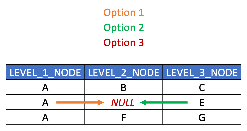
Note that relaated columns are absent from this example just for illustration purposes (such as HIERARCHY_ID, SEQNR, TEXT and LEAF_NODE columns.)
And lastly, in terms of handling unbalanced hierarchies in a level structure, the typical approach is:
- As with all level hierarchies, extrapolate leaf node values (regardless of what level they’re at) into a dedicated LEAD_NODE column (or LEAF_NODE_ID column), and
- Populate the empty level columns with either NULL or PLACEHOLDER values, or potentially extrapolate the nearest ancestor values down through the empty levels (if business requirements dictate as much).
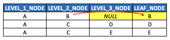
Note that required columns are absent from this example just for illustration purposes (such as HIERARCHY_ID, SEQNR and TEXT columns.)
Concluding Thoughts
Over the course of this series, we’ve covered quite a bit of ground when it comes to hierarchies (primarily, but not exclusively, in the context of BI and data warehousing), from their foundational principles to practical data modeling approaches. We started our discussion by introducing graphs and directed acyclic graphs (DAGs) as the theoretical basis for understanding hierarchies, and we built upon those concepts by exploring parent-child hierarchies, level hierarchies, and the tradeoffs between them.
As a consequence, we’ve developed a fairly robust mental model for how hierarchies function in data modeling, how they are structured in relational databases, and how they can be consumed effectively in BI reporting. We’ve also examined edge cases like ragged and unbalanced hierarchies, heterogeneous hierarchies, and time-dependent (slowly changing dimension) and versioned hierarchies, ensuring that some of the more complex concepts are explored in at least some detail.
Key Takeaways
To summarize some of the most important insights from this series:
- Hierarchies as Graphs – Hierarchies are best conceptualized as a subset of DAGs, which themselves are a subset of graphs. Understanding how to models graphs and DAGs makes it easier to understand how to model hierarchies (including additional attributes such as LEVEL and SEQNR).
- Modeling Hierarchies – There are two primary modeling approaches when it comes to hierarchies: parent-child and level hierarchy models. The flexibility/reusability of parent-child hierarchies lends itself to the integration layer whereas level hierarchies lend themselves to the consumption layer of a data platform/lakehouse.
- Flattening Hierarchies – Transforming parent-child hierarchies to level hierarchies (i.e. “flattening” hierarchies) can be accomplished in several ways. The best approach is typically via recursive CTEs, which should be considered an essential skills for Data Engineers.
- Hierarchies Are Everywhere – Hierarchies, whether explicit or implicit, can be found in many different real-world datasets, and many modern file formats and storage technologies are modeled on hierarchical structures and navigation paths including JSON, XML and YAML. Hierarchies also explain the organization structure of most modern file systems.
- Hierarchy Design Must Align with Business Needs – Theoretical correctness means little if it doesn’t support practical use cases. Whether modeling financial statements, org charts or product dimensions, hierarchies should be modeled, evolved and exposed in a fashion that best aligns with business requirements.
I genuinely hope this series has advanced your understanding and skills when it comes to hierarchies in the context of data engineering, and if you find yourself with any lingering questions or concerns, don’t hesitate to get in touch! LinkedIn is as easy as anything else for connecting.